壓力感應 再生 安裝組件
FACE 7
FUNCTION
B to A
技術特性
CAD文件
技術數據
常見問題
備注
額外來源
Included Components
全部收起
技術特性[ - ]
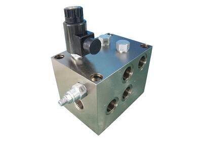
The pressure sensitive regenerative valve assembly allows a double-acting, single rod cylinder to be extended more rapidly using the same pump flow. To achieve this, oil from the rod end of the cylinder is added to the pump flow to the blind end, increasing the rate of extension. It incorporates a pressure adjustable, counterbalance valve that provides a smooth transition when the load is engaged and pressure in the blind end rises to approximately 25% of the set point of the counterbalance valve, at which time the regenerative flow decreases smoothly until rod end flow is fully diverted to tank. Full pump pressure is then applied to the blind end area developing maximum force.
Capacity refers to pump flow or regeneration flow, which is the flow coming out of the rod side of the cylinder, whichever is larger
This valve assembly will not prevent a load from extending the cylinder. The best way to prevent this is to use a vented counterbalance valve mounted directly to the rod end of the cylinder. A non-vented valve will not work.
The ideal cylinder ratio to use with regeneration is 2:1, the blind end area being twice what the annular area at the rod end. A 2:1 cylinder in regen gives the same speed extending as retracting.
Cylinders with ratios above 2:1 (large rods) will function correctly but with less speed gain. Intensification needs to be considered with higher ratios. A 2:1 cylinder may generate a pressure on the rod side that is twice system pressure unless steps are taken to limit it.
Cylinders with ratios as low as 1.5:1 (small rods) may work if care is used in designing the application. As the rod diameter gets smaller in relation to the piston diameter the flows increase dramatically and the force available drops accordingly.
Cylinders with ratios below 1.5:1 are unlikely to result in a working regenerative application because of the small area of the rod and the high flows that would be generated.
When a cylinder is in the regenerative mode the only force available is the pressure working on the rod area.
The counterbalance valve in this assembly is not acting as a counterbalance valve; it is acting as a pressure sensitive unloading valve. The setting, however, relates to the counterbalance world. With the CB*A set at 4000 psi (280 bar), the circuit will start to come out of regen with about 1000 psi (70 bar) of blind end pressure and will then start to gain force somewhere above 1400 psi (90 bar).
Regeneration is only possible in the extend direction.
回到首頁
CAD Files[ - ]
Model CAD Files
Click the link of the file format you want to download.
YDESLHNBA_1.dwg
YDESLHNBA_2.dwg
YDESLHNBA_3.dwg
YDESLHNBA_4.dwg
YDESLHNBA_5.dwg
YDESLHNBA_6.dwg
YDESLHNBA_7.dwg
YDESLHNBA_8.dwg
YDESLHNBA_1.dxf
YDESLHNBA_2.dxf
YDESLHNBA_3.dxf
YDESLHNBA_4.dxf
YDESLHNBA_5.dxf
YDESLHNBA_6.dxf
YDESLHNBA_7.dxf
YDESLHNBA_8.dxf
YDESLHNBA.prt
YDESLHNBA.stp